Example Set-Up
Example Set-Up
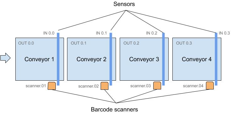
This example setup describes the movement of containers over conveyors. The conveyors have motors which can be started and stopped by a GPIO output pin controlled on a Raspberry Pi and each conveyor has a light barrier to detect the occupancy of a container and the Raspberry Pi detects this on GPIO input pins.
Further at each conveyor location is a barcode reader to read the ID of a container.
The general idea is that the PLC notifies a Strolch agent of changes, and only turns conveyors on, when the agent gives the command. Thus the agent handles business logic and the PLC controls the I/Os.
New Project
Create a new project using the PLC Strolch Maven Archetype:
mvn archetype:generate \
  -DarchetypeGroupId=li.strolch \
  -DarchetypeArtifactId=strolch.mvn.archetype.plc \
  -DarchetypeVersion=0.4.0 \
  -DgroupId=<my.groupid> \
  -DartifactId=<my-artifactId> \
  -Dversion=<my.version> \
  -Dpackage=<my.package> \
  -DappName="<my app name>"
This will create a multi-module project:
- The
<my-artifactId>-webmodule contains the server code, which handles notifications from the PLC, and can send telegrams to the PLC. - The
<my-artifactId>-plc-webmodule contains the PLC code, which connects to the server and communicates with the low-level hardware. - The
sharedmodules contains classes shared by both projects (e.g. constants, etc.).
This project already contains a default PLC model in <my-artifactId>-plc-web/runtime/data/.
The following sections explains these files:
strolch-plc-example-connections.xml
This file defines the hardware connections. The following connections are implemented:
- li.strolch.plc.core.hw.i2c.RSL366OverHorterI2c
- li.strolch.plc.core.hw.i2c.PCF8574InputConnection
- li.strolch.plc.core.hw.gpio.RaspiBcmGpioInputConnection
- li.strolch.plc.core.hw.gpio.RaspiBcmGpioOutputConnection
- li.strolch.plc.core.hw.i2c.Multi8BitI2cOutputConnection
- li.strolch.plc.core.hw.connections.DataLogicScannerConnection
- li.strolch.plc.core.hw.connections.LoggerOutConnection
- li.strolch.plc.core.hw.connections.RandomStringConnection
See their respective classes for details.
strolch-plc-example.csv
This file maps I/Os to Resources and Actions and is converted into Strolch Resource objects using
the PlcAddressGenerator class.
In this example we will use simple Raspberry Pi GPIOs. For convenience, and also when sharing I/O definitions with
external partners, it is easier to use a CSV file to define the I/Os and then use the PlcAddressGenerator to generate
and validate the model.
For easier handling, use the following Google Sheet as a starting point: https://docs.google.com/spreadsheets/d/10fgTfR3FZCVbQ5bbh0xB1u8rLIaw2KEyO45VMv7y5ho/edit?usp=sharing
The CSV headers are as follows:
- Description → a simple description for this PlcAddress
- Type →
- Group → Must be the first line and generates a PlcLogicalDevice, all succeeding lines are grouped to this device. Add additional to group further devices
- Input → defines a boolean input
- Output → defines a boolean output
- Virtual → defines a virtual address which has no corresponding hardware connection. Used for internal communication.
- DataLogicScanner → defines an address to read barcodes from a DataLogic Scanner. The actions must be left empty as the keys Barcode (address), On and Off (telegrams) will be generated.
- SubType →
- For Input and Output types →
- DevPin, DevPin0 → Generates the address as
<Connection>.<Device>.<Pin>. DevPin0 decrements the Device and Pin values by one for zero-indexed addressing. - Pin → Generates the address as
<Connection>.<Pin>.
- DevPin, DevPin0 → Generates the address as
- For Virtual types →
- Boolean
- String
- Integer
- For Input and Output types →
- Device → Device number
- Pin → The pin number on the device
- Resource → The resource ID with which to notify the agent
- Action1 → The action ID
- Action2 → The second action ID if required
- Connection → The ID of the PlcConnection with which this I/O is attached
- DeviceId → For type Group: Set the ID of this PlcLogicalDevice being generated
- Interted → For boolean inputs or outputs, if true, inverts the value
- Value → A default value, often used for virtual integer addresses
- Remote → if true, then the server will be notified of changes to this address
When you use this file as input for the PlcAddressGenerator, then it will
generate PlcLogicalDevice, PlcAddress and PlcTelegram elements. See the file strolch-plc-example.xml for an example.
The PlcLogicalDevice references the PlcAddress and PlcTelegram objects, and is
then used in the UI for grouping.
The PlcAddress is used to store the current value and defines the keys with
which the agent will be notified
The PlcTelegram is used to store default values to send, for specific keys. E.g.
The action On would send true, and Off would send false. This is semantics, and
is defined in each project depending on the hardware.
Running the example
Once you have both the server and PLC instances running, you can login. The default username and password are admin
/ admin.
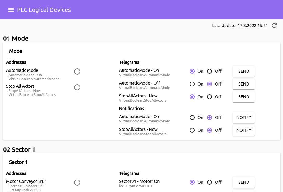
After logging in to the PLC you should be greeted with the following
screen:
And after logging in to the server you should be greeted with the following
screen:
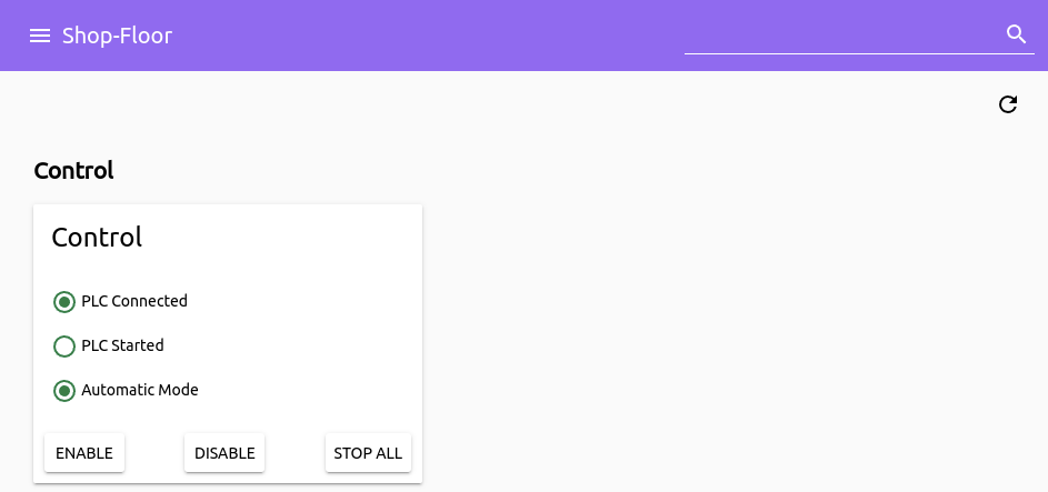
If the PLC could connect to the server, then the PLC Control icon should be activated. The actions Enable, Disable and
Stop All send telegrams to the PLC, thus showing how the server would communicate with the PLC.
Customization
PLC
Now that the server and PLC are running, we can customize the code. On the PLC side you will want to create
new li.strolch.plc.core.PlcService services by extending the class and then registering the service
in CustomPlcServiceInitializer.
See the example StartupPlcService.
Server
On the server side, to register for notifications from the PLC, one would
implement li.strolch.plc.gw.server.PlcGwService services and register them on the PlcHandler in
the PostInitializer class.
See the example ModePlcSrvService.